We present many ideas here on VillageHaunt.com. Many of these ideas involve potentially dangerous project building and using tools that may have their own unique hazards as well. While we do hope you enjoy your reading about these interesting projects and activities, Tracy Murphy of VillageHaunt.com assumes no responsibility for any damages/injuries following these instructions may cause you or others of any kind. If you choose to use products in a way that the manufacturer didn't intend for it to be used as shown herein, you alone take full responsibility for any damages you may sustain. Many of our projects here require very hazardous tools and applications of tools that the novice or even the professional may not be able to use without some level of bodily/property damage.
 This is the
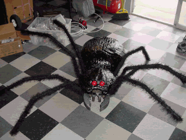
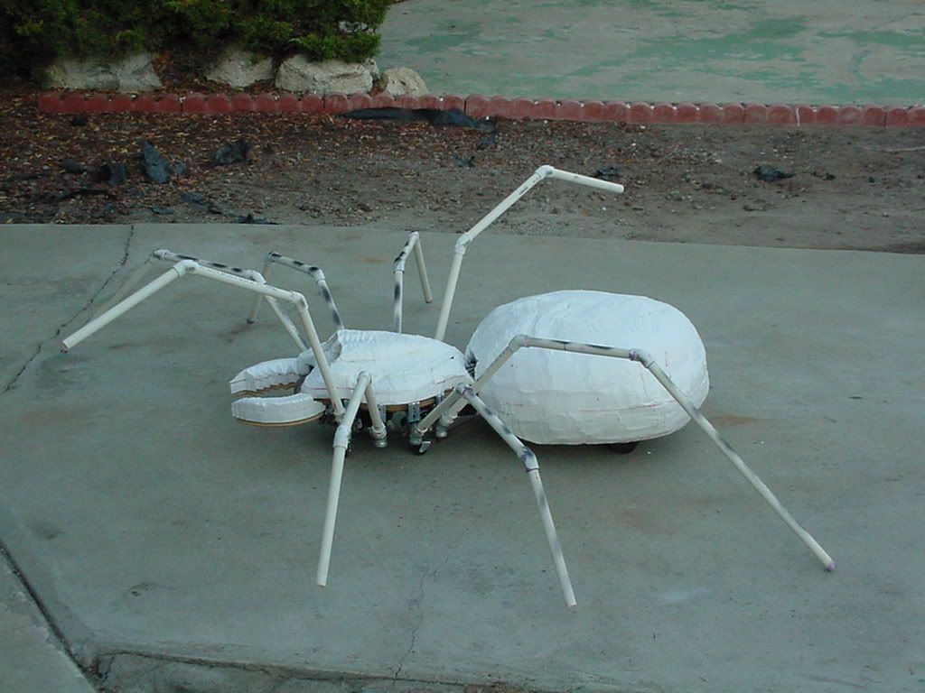
first prop I ever made using a WINDSHEILD WIPER MOTOR. This is also the first Spider Prop I have ever made. Hopefully these instructions will help others to advance their
Home Haunts.Please use these plans, but don't forget
to link my site (www.villagehaunt.com) as the
original Wiper~Motor Spider. July 3rd 2006. Questions? village_haunt@yahoo.com
This is the
first prop I ever made using a WINDSHEILD WIPER MOTOR. This is also the first Spider Prop I have ever made. Hopefully these instructions will help others to advance their
Home Haunts.Please use these plans, but don't forget
to link my site (www.villagehaunt.com) as the
original Wiper~Motor Spider. July 3rd 2006. Questions? village_haunt@yahoo.com
BEHIND THE SCENES VIDEO >>> 
 <<<< Assembly
video Tear-down
video >>>>
<<<< Assembly
video Tear-down
video >>>> 
 <<<< Programming video Part
1 ............ Part 2 >>>>
<<<< Programming video Part
1 ............ Part 2 >>>> 
|

-
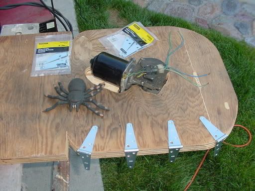
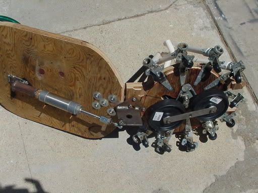
I started with this little rubber spider as my model

-
Here is my start, a FREE wiper motor from an 86 Suburu and some hardware from ACE.

-
Here is the Wiper and basic wheel assembly together.

-
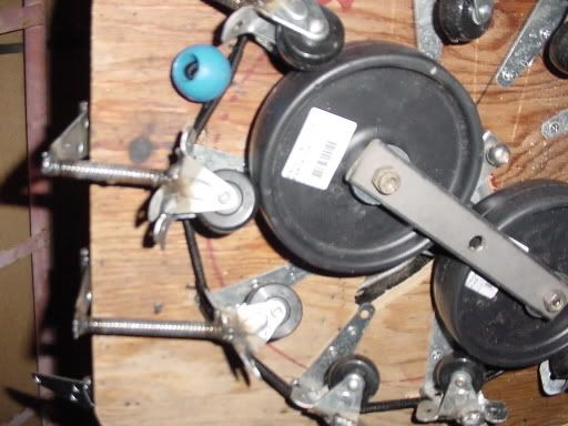
I used a thick piece of of plywood as my base, and I fit the wiper motor in so that it would sit low profile.

-
Here is a pic of the wiper/wheel assembly mounted to the wood base.

-
Next I spaced and mounted 10 hinges to the base.

-
Then I welded 10 small wheels to the hinges.

-
I used a tiny bungee band around the 10 hinges to force them back to their upright positions.

-
Here is a small 1.3MB video clip of the mechanical heart running through 4 speeds.
![]()
![]() IT IS QUITE
ROBUST!!!!
IT IS QUITE
ROBUST!!!!
Part 2 The Bad Idea
*Do not follow instructions in Part 2 (see revised instructions in Part 3)
I started this part on July 07, 2006
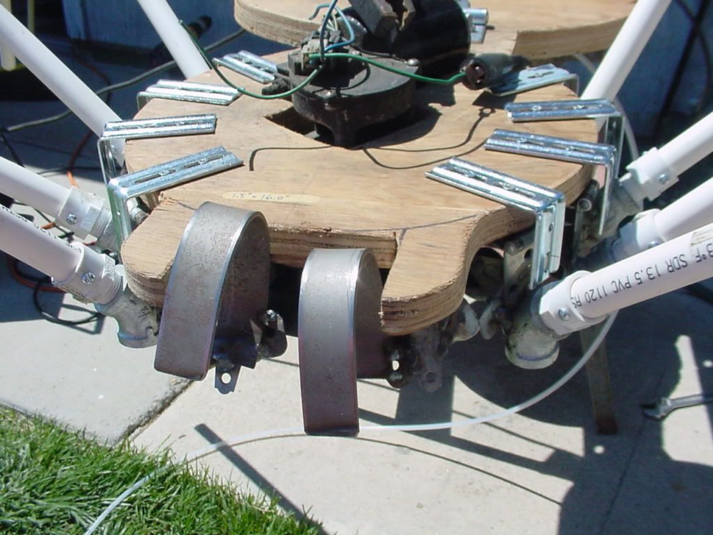
I added more hinges around the outside*
Then I chopped pieces off of my 3/8 plumbing snake and used them as flexable push rods*

Here is a little video clip of the Spider running with push rods*
*Do not follow instructions in Part 2 (see revised instructions in Part 3)
Part 3 Revision B
Today (
07/08/2006) I tore down and rebuilt.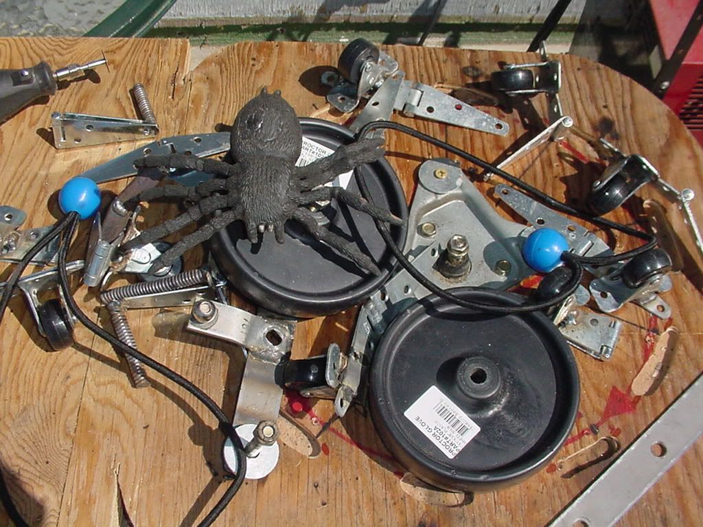
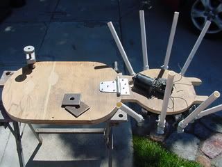
What a mess! As you can see, the Spider is DEAD...

First, I got the saw out and put this thing on a diet!

Then, I mounted all the rockers back into new positions.

Next, I mounted and test the CAM. (see picture, as it is a video link)

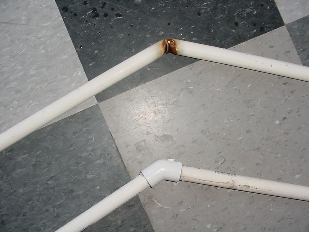
I welded on some metal elbows to receive the PVC legs.
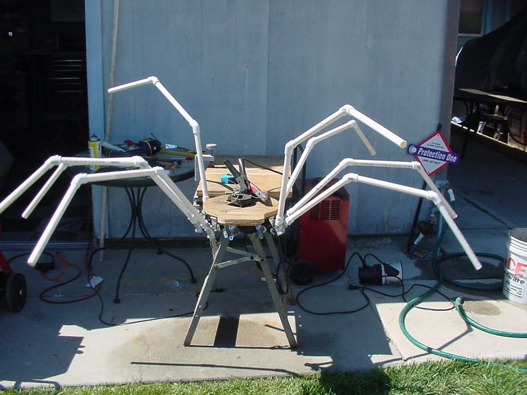
Then I put on the PVC legs. Made from 3 one foot pieces of PVC and two 45 degree elbows.

Here is SpiderWiper hard at work.... (see picture, as it is a video link)
Part 4 The Pivot


|


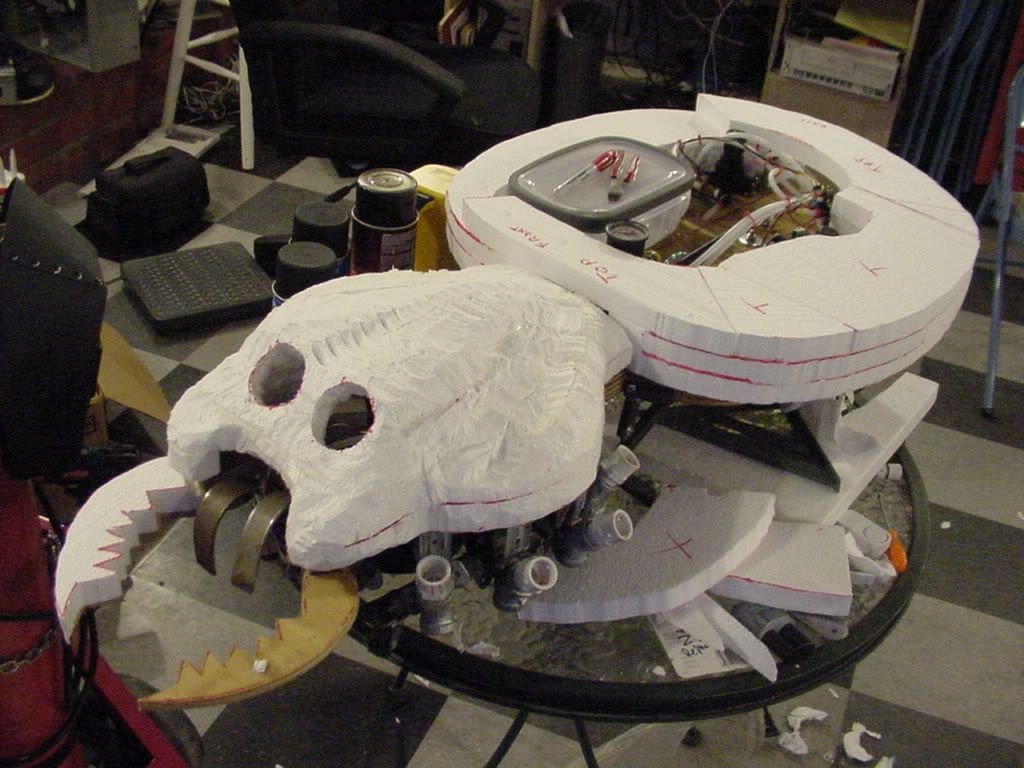
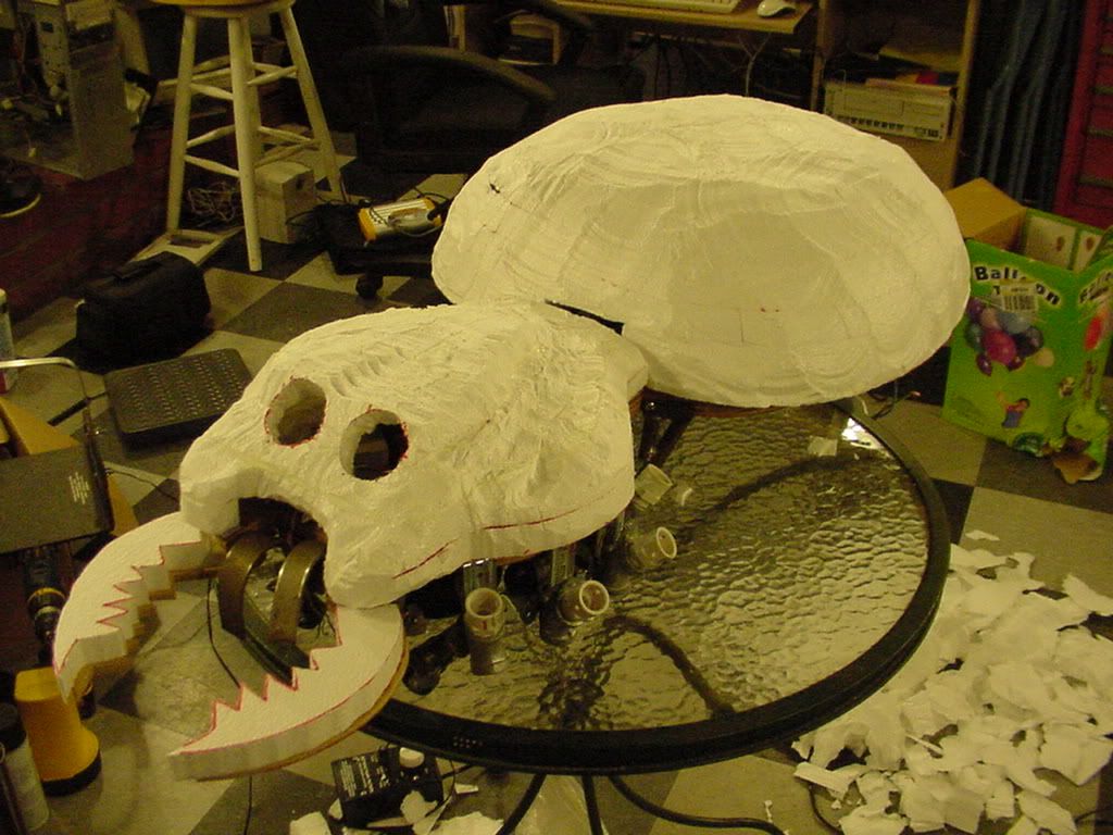
Part 5 Jaws
July 16th, 2006


|
|
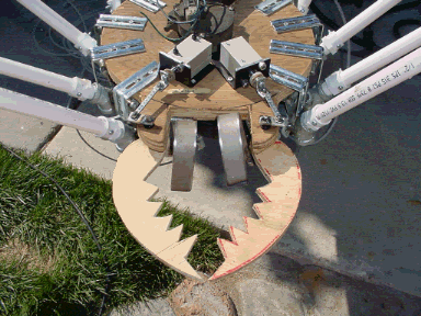
![]() PLACE YOUR HEAD HERE
PLACE YOUR HEAD HERE ![]()


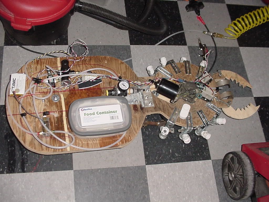
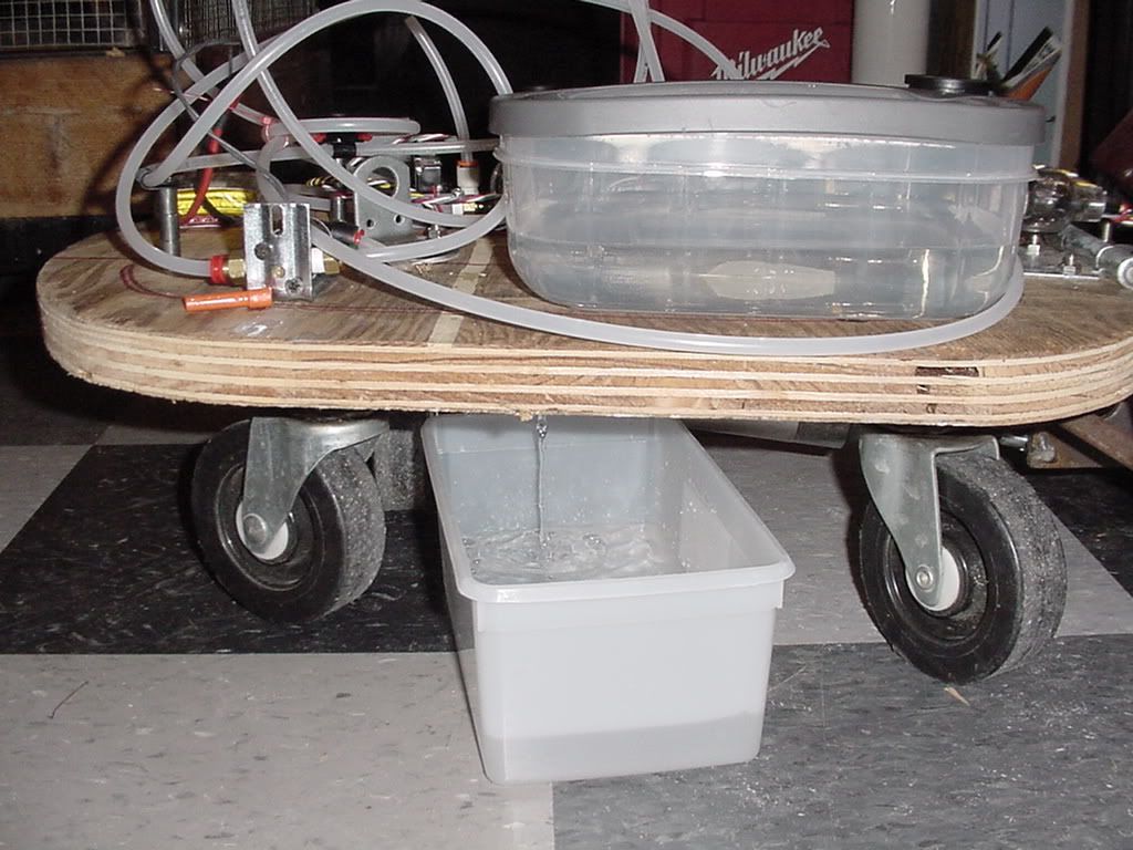

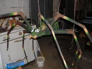
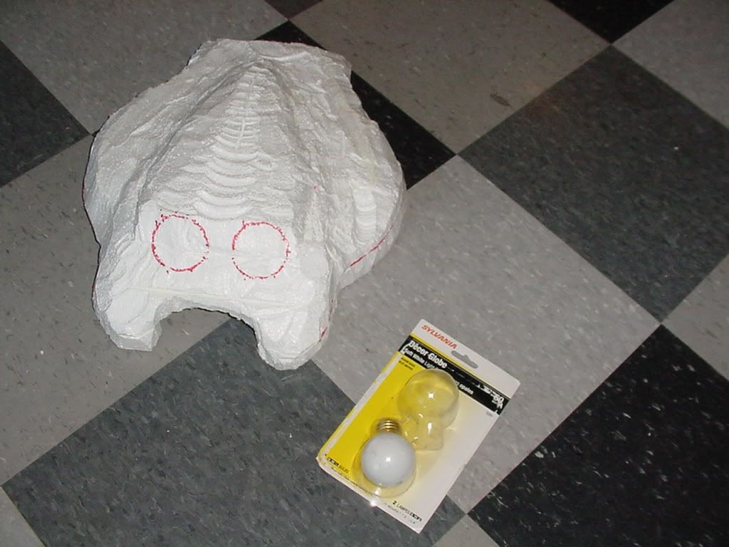
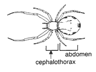
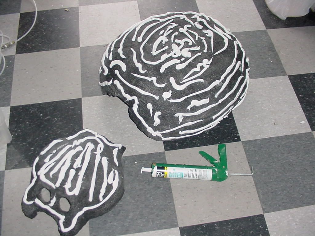
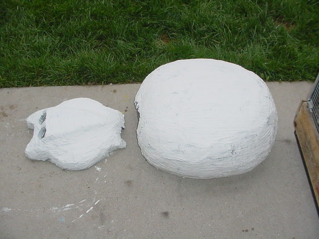
Part 7 The Spider Body
August 05, 2006


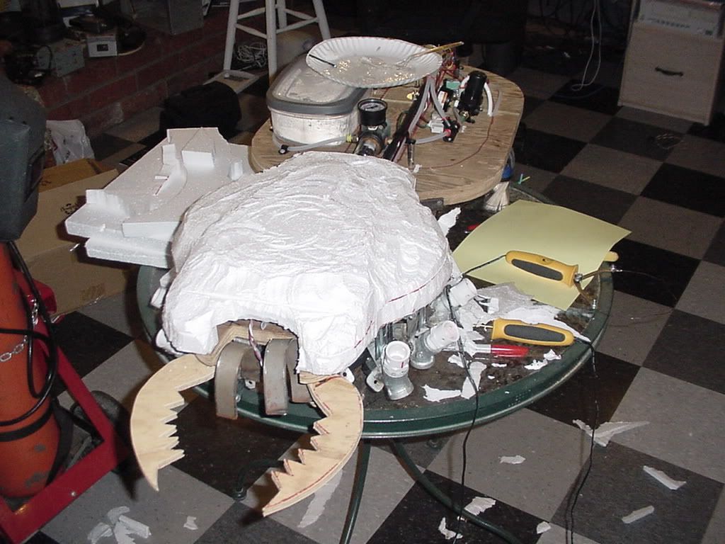


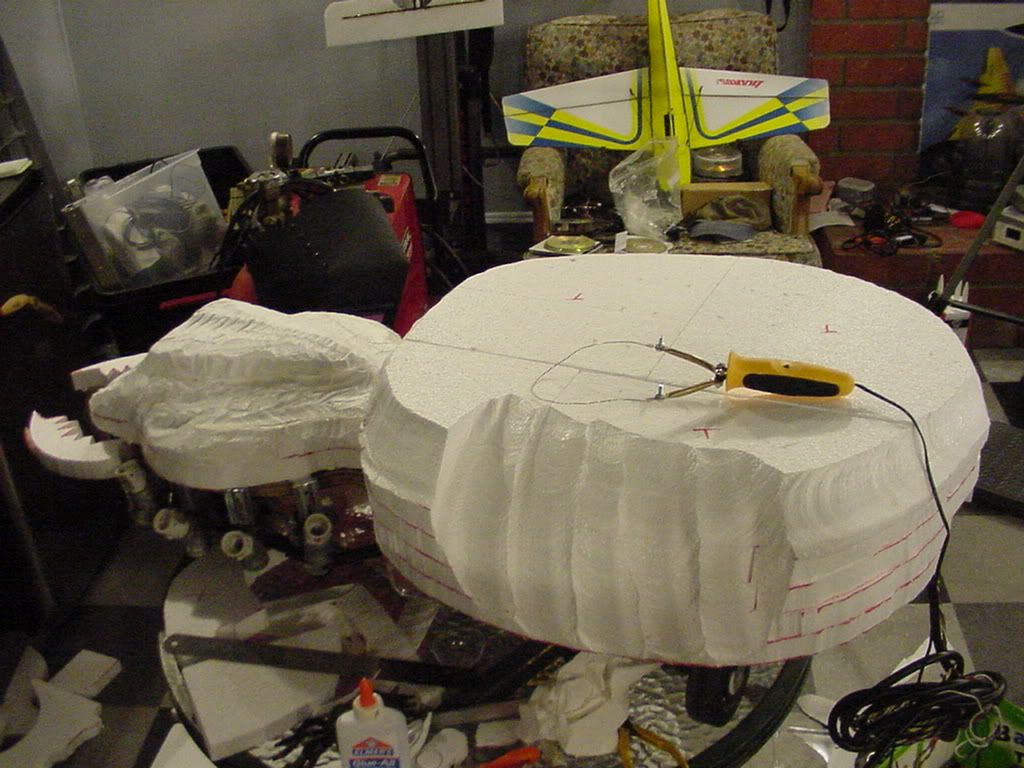

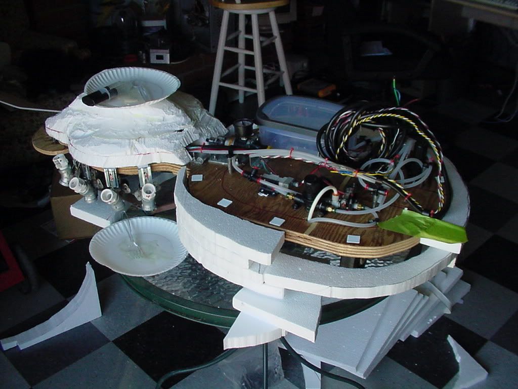
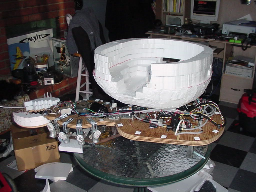
Part 8 Nothing But Leg
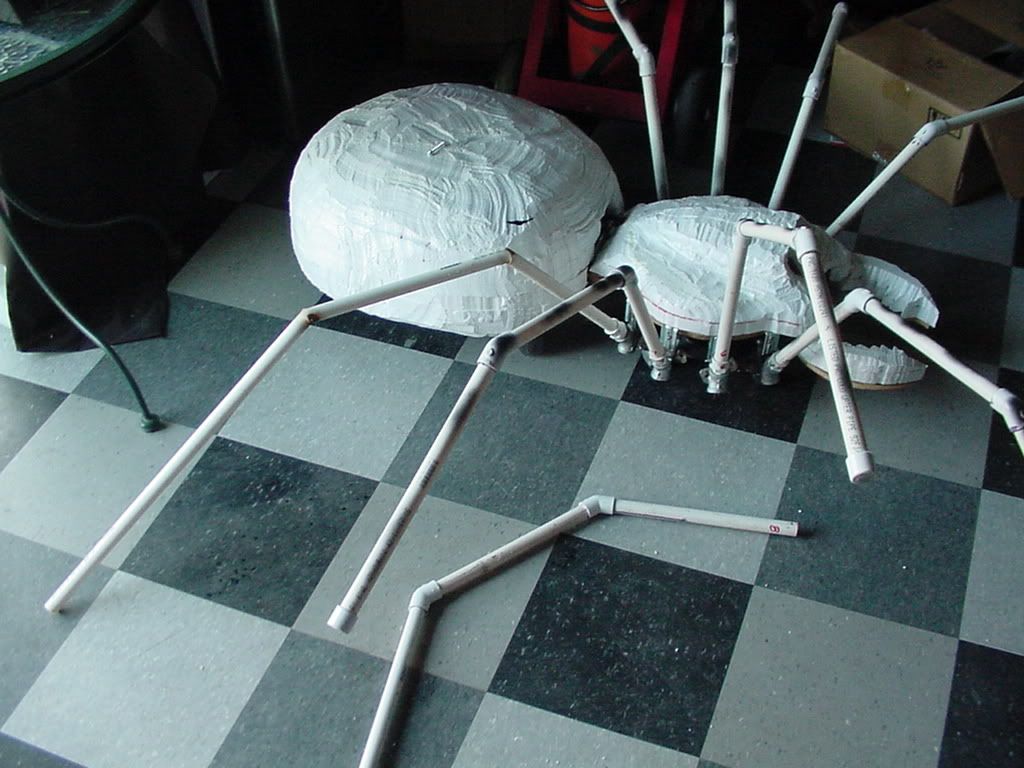

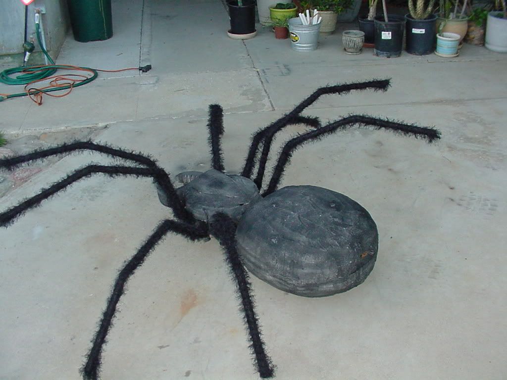
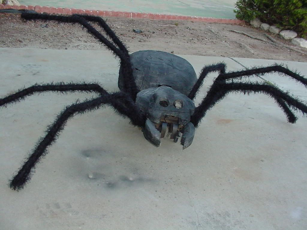
Part 9 Body Work
(August 19, 2006)

Part 10 Simple Drive REV-A
(August 24, 2006)
*Do not follow instructions in Part 2 (see revised instructions in Part 11)
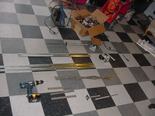
*I don't know how, but I know it's gonna take some metal.
*I layed it all out and sat and thought... (for a really long time)
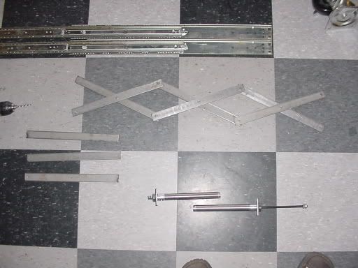
*I thought I would weld two draw slides together.
*Like so...
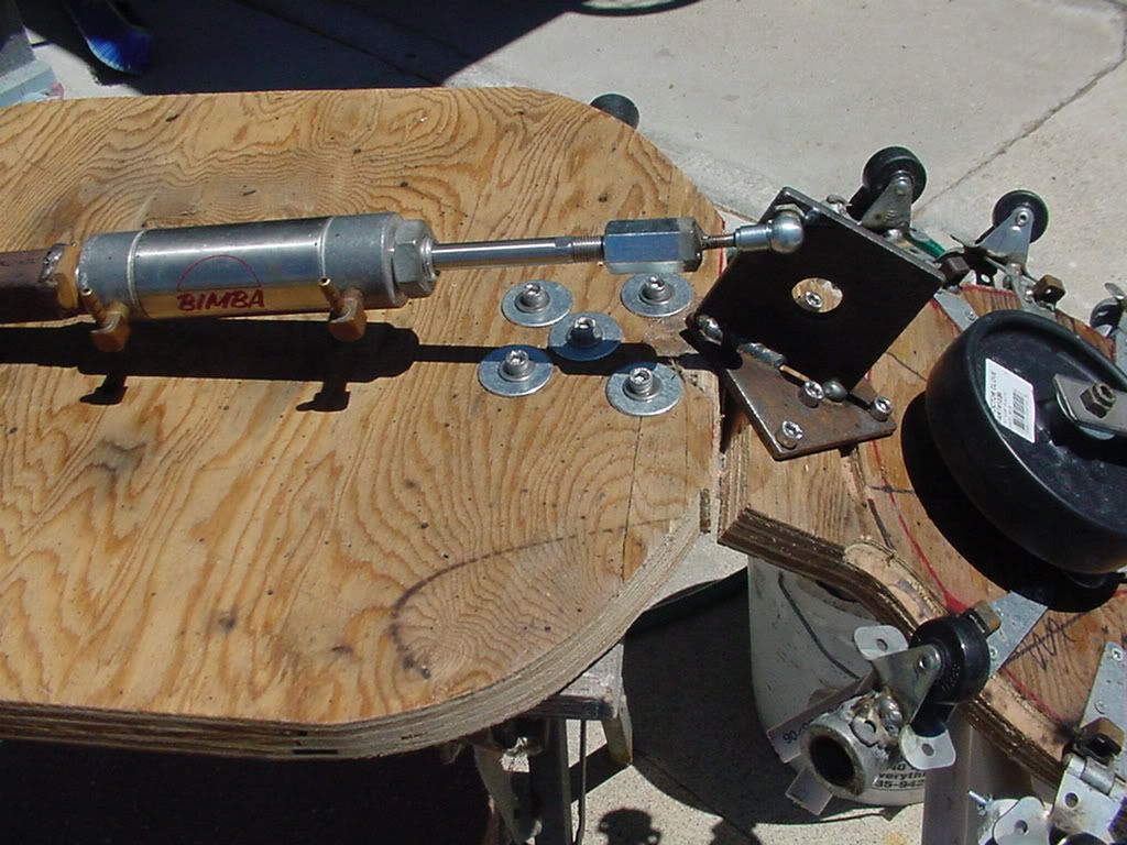
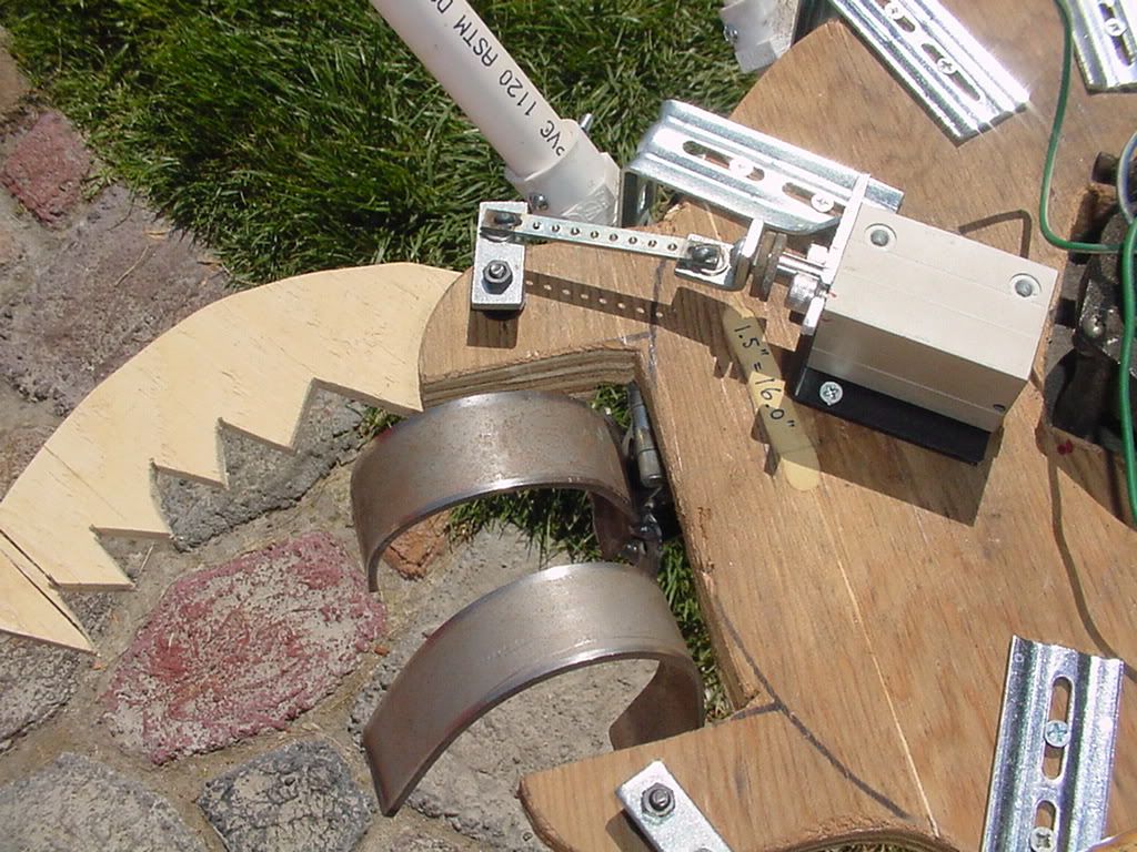
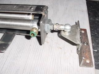
*Then I mounted my 14 inch Bimba cylinder.
*Oh it looks so nice!
*Here is a picture of it fully extended.
This is the last you will see of this design, as it is now at the landfill. My big mistake was the pneumatic travel exceeded the draw slide travel. After a couple cycles, there was ball bearings flying everywhere.
*Do not follow instructions in Part 2 (see revised instructions in Part 11)
Part 11 Simple Drive REV-B
(August 25, 2006)
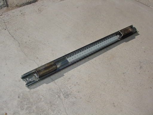
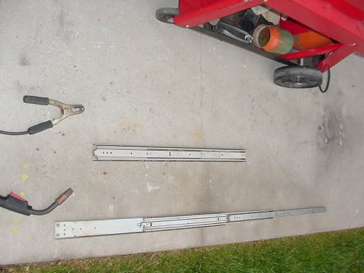
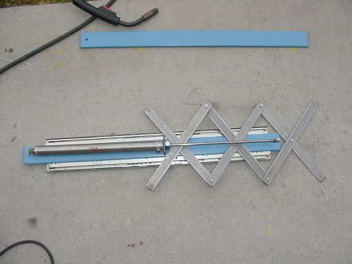
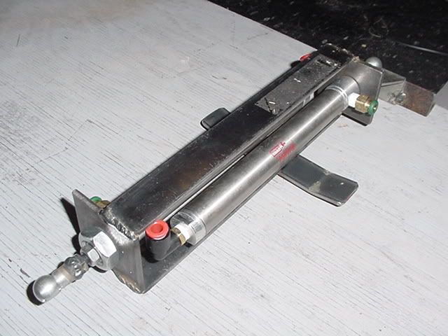
I got three more draw slides, but this time I am going to stack them.
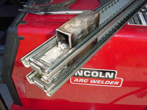
In this picture you can see I fused two slides together... (I think I am on to something)
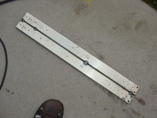
OK, I jumped ahead a tiny bit. All three draw slides are now stacked and the Bimba cylinder and expansion linkage is mounted.
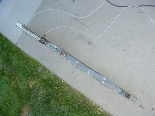
Oh, by the way, the expansion straps are 12 inches long. Retracted length 2 feet, extended 5 feet.

Here is a little video clip of it in action.
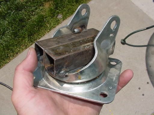
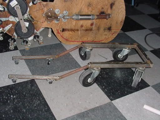
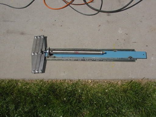
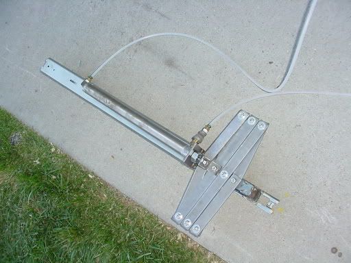
I hacked a large caster to give the Simple Drive the ability to pan left or right.

Here it is all welded into place.
Here is a close-up of the Panning Drive's mount.
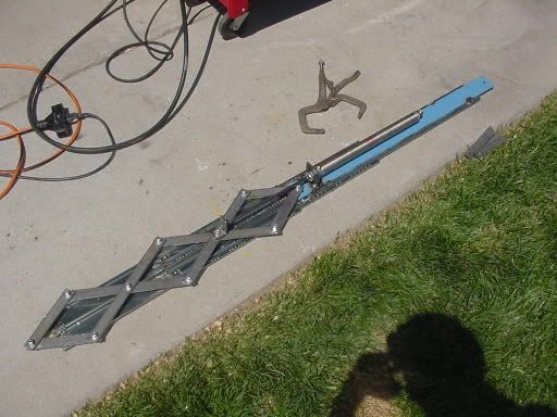
Two opposing cylinders will give me the ability to go from center to left or right and back to center.

Here is a short video animation show this drives future movement ability.
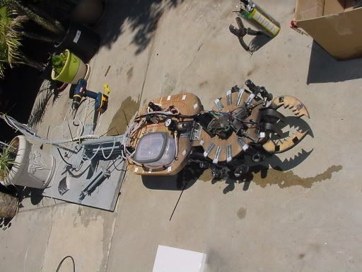
Here is a picture of the Spider~Wiper linked to the Simple Drive.
MAN THIS IS GETTING TO BE A RIDICULOUS PROJECT!!!
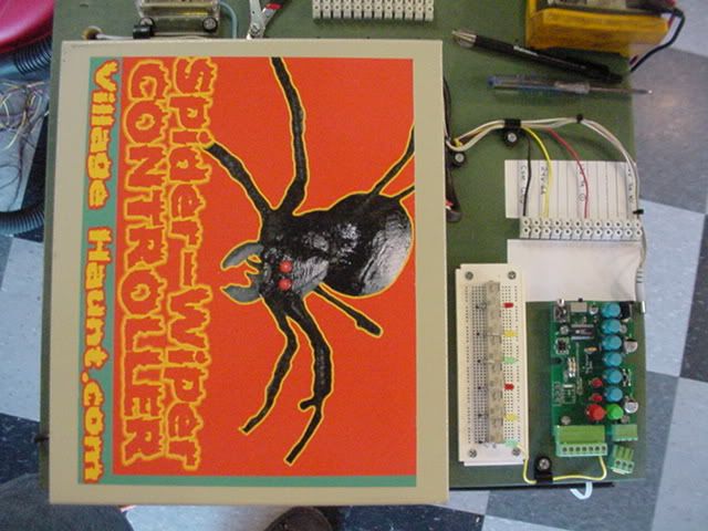
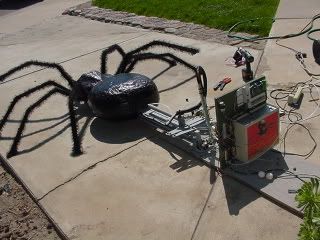
Part 12 The Spider Controller
(09/03/2006)

Gotta have a graphic.

The brains to my controller, is the new Key Banger from Sprawling Delusions.

This thing is awesome!
(From the Sprawling Delusions site) The OEM Delusional Key Banger with audio is a six channel prop controller that you use by recording your desired sequence by pressing or banging on the six blue function keys. Once your sequence is recorded the Key Banger will play your recorded sequence whenever the green GO button is pressed or the optional passive infrared motion sensor detects movement. However, if you prefer you can remove a jumper and the Key Banger will continually play your sequence in a loop. 4+ minute record time Comes with wall adapter Outputs are rated at 24 volts DC Max combined current draw of the outputs is ¾ amp Optional PIR Sensor is part number PIR-1
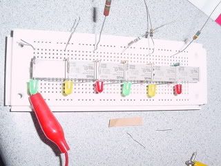
I used a bread board for my 1st stage relay board. I am using six 24v relays.
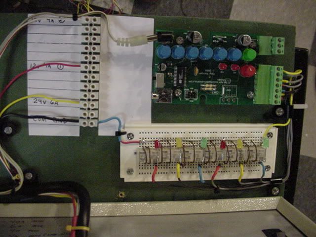
The relay bread board hooked into the Key Banger Module. I added diodes for a little cheap insurance and some LED's to see the relays come on.
I mounted a BIG power supply on an old piece of wood. Painted green to help keep my sanity.
Here is an overview shot before all the wiring was completed.

Here is a tiny video showing the Key Banger running a program to the relays.
I just got to say the Key Banger is SUPER easy to program and it really KICKS butt in REAL TIME!
NO COMPUTERS NEEDED!
I love the 2 units I own!
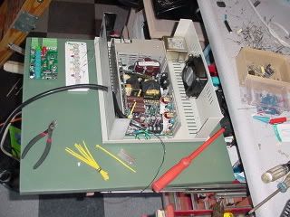
Part 13 It's Alive
What a mess... but it works.
|
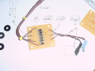
I added 6 diodes so that the legs circuit will be on whenever any of the 6 Key Banger channels are operating.
|
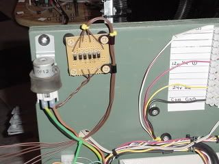
Here is my new diode board mounted next to my leg operation relay.
|
|
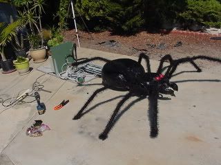
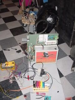
YAHOOO it is almost done!
|

>>>>CLICK THE VIDEO AND CHECK IT OUT<<<<
It works, but I still have a long way to go before it is done...